Installation & Wiring
This guide shows how to connect your board to the CAN bus on a Tesla Model 3/Y. The easiest method is using an Enhance Auto Tesla Gen 2 Cable — the same cable used for the Enhance Auto S3XY Commander — which provides both CAN bus data and 12V power through a single connector.
This guide is board-agnostic — it applies to any board you're using with this project.
What You Need
| Part | Link |
|---|---|
| Enhance Auto Tesla Gen 2 Cable | enhauto.com |
| 12V/24V to 5V DC/DC Converter (USB-C or Micro-USB, depending on your board) | Various suppliers |
Step 1: Access the X179 Connector
The X179 connector is located on the passenger side footwell, behind the panel on the right.
- Remove the right-side footwell panel trim — it pops off with gentle pulling, no tools required.
- Locate the connector cluster. The X179 connector is the one highlighted below.

For a video walkthrough of how to access the connector and plug in the cable, see this installation video by Enhance Auto.
Legacy Model 3 vehicles (2020 and earlier) may not have the X179 connector. In that case, use the X652 connector — CAN-H on pin 1, CAN-L on pin 2.
Step 2: Identify the Cable Pinout
The Enhance Auto Gen 2 Cable has a connector on one end that plugs into the X179 port, and loose wires on the other end that normally connect to a S3XY Commander. The pinout of the loose end:
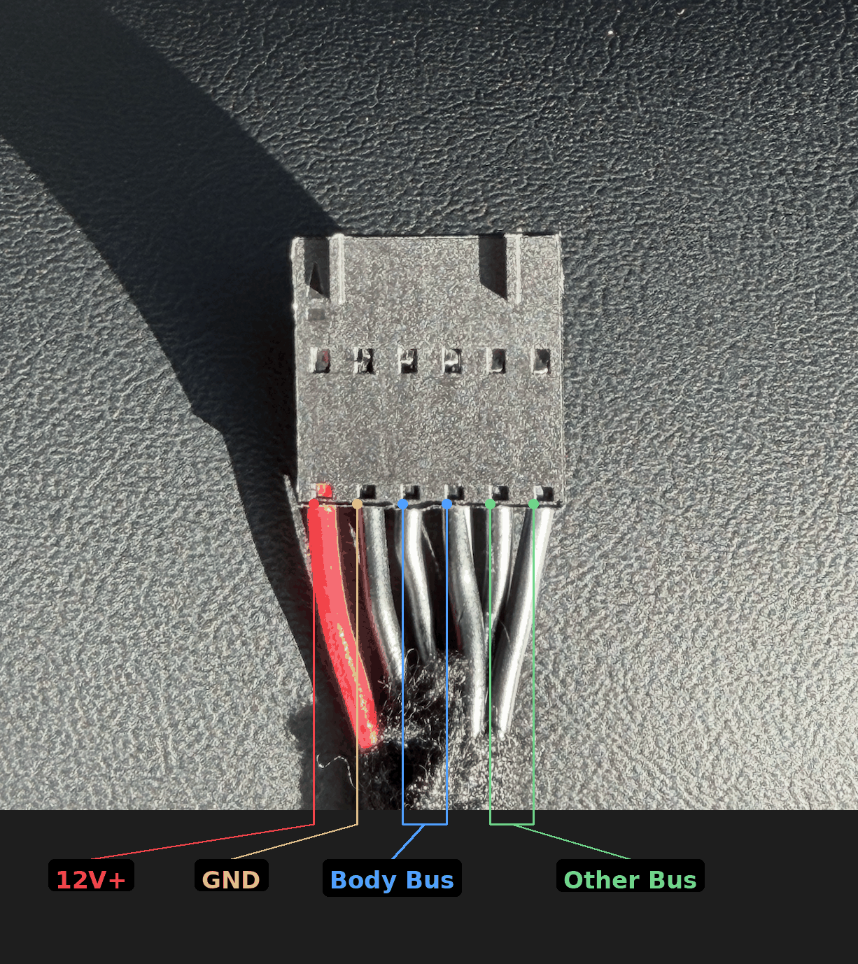
| Wire | Signal | Purpose |
|---|---|---|
| Red | 12V+ | Power — connect to DC/DC converter IN+ |
| Black | GND | Power — connect to DC/DC converter IN- |
| Black with stripe | CAN-H (Body Bus) | CAN bus — connect to your board's CAN-H |
| Black solid | CAN-L (Body Bus) | CAN bus — connect to your board's CAN-L |
| Remaining black pair | Other Bus | Not used — leave disconnected |
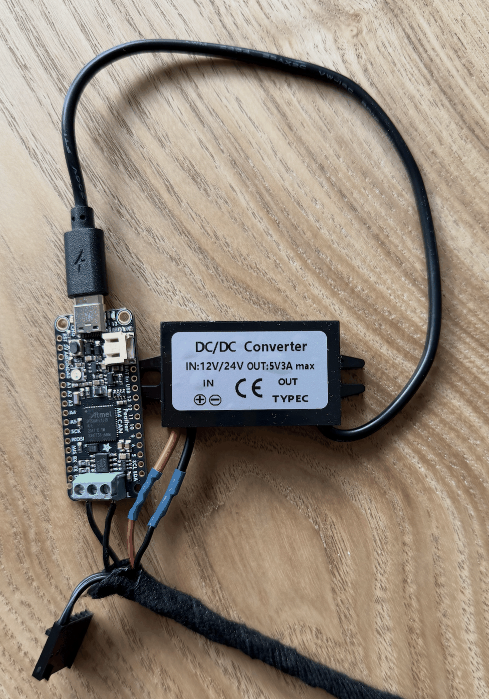
Step 3: Connect Power and CAN Bus
- Connect the CAN-H (black with stripe) and CAN-L (black solid) wires to your board's CAN screw terminal or CAN pins.
- Connect the 12V+ (red) and GND (black) wires to your DC/DC converter's input.
- Connect the DC/DC converter's output (USB-C or Micro-USB) to your board to power it.
If your board or CAN module has an onboard 120 Ohm termination resistor, cut or remove it before connecting. The vehicle's CAN bus already has its own termination, and adding a second resistor will cause communication errors.
Step 4: Plug Into the Car
Plug the Enhance Auto cable into the X179 connector. It clicks into place — no jumper wires, soldering, or splicing needed.
The cable provides both CAN bus data and 12V power through the single connector, so your board will power on as soon as the car wakes up.
Direct Wiring (Without Enhance Auto Cable)
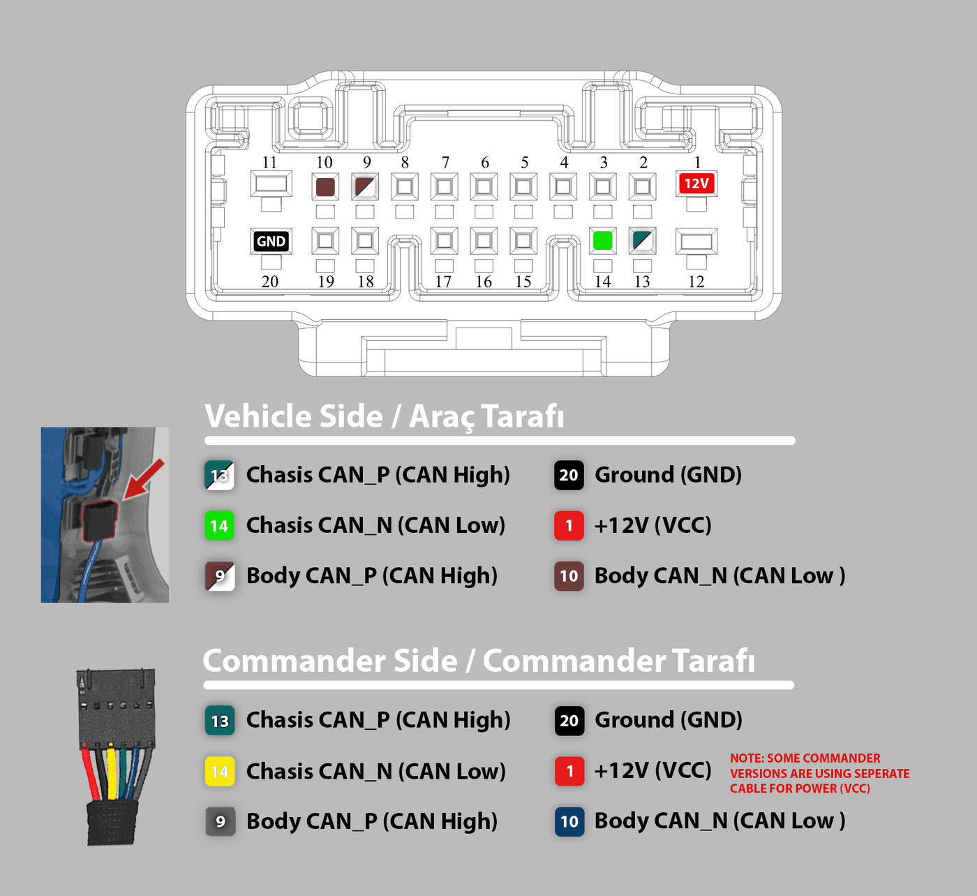
If you prefer to wire directly, connect to the X179 connector pins:
| Pin | Signal |
|---|---|
| 13 | CAN-H |
| 14 | CAN-L |
For legacy Model 3 (2020 and earlier), use the X652 connector:
| Pin | Signal |
|---|---|
| 1 | CAN-H |
| 2 | CAN-L |
Note that with direct wiring you will need to provide power separately.